Theoretical Basis
Rotor Imbalance
During the last decade the wind energy technology has undergone an impressive development in terms of structural dimensions, power output and reliability. With this development rotor diameters and hub heights of up to 138 m respectively 150 m were reached. Therefore, the rotating forces of the rotor increased and the corresponding requirements of all components to endure the higher dynamic loads. With the economic necessity of component dimensioning with tight safety margins the components are not designed to withstand larger extra stress caused by extra dynamic fatigue loads, which are caused e. g. by rotor imbalance. From early on, standards [IEC61400-1] and guidelines [GL, DIBt] for the certification of wind turbines required the turbine manufacturer for the design simulations to state admissible limit values for mass imbalance, e.g. uneven mass distribution in the rotor, and aerodynamic imbalance from blade angle and blade twist differences. The resulting excess forces have to be included in the design life simulations for operational fatigue analysis. The requirement is that during the turbine entire operation, these admissible limit values shall never be exceeded.
This shows that turbine design standards and guidelines mention already two types of imbalance, which cause excess-vibrations related to the rotors’ rotational speed which superimpose, therefore they have to be investigated separately. Nevertheless, during in-situ balancing vibration measurements of wind turbine rotors, the falsifying impact of aerodynamic imbalance was often ignored. Moreover, there are various root causes for mass and aerodynamic imbalance. The forces resulting from both types of imbalance superimpose, and the aerodynamic imbalance falsifies a vibration measurement for mass imbalance detection. The resulting vibrations are directly conducted into the drive train’s bearings, gearbox, generator and through the nacelle frame and tower structure even in the tower foundation. An exceedance of the fatigue design limits of the particular components can lead to a faster consumption of lifetime and even total loss of the components. The design limits of the rotor’s mass imbalance is a value for its mass eccentricity in kg*m, not a vibration value since the vibration varies with rotor speed. As mentioned above, the admissible limit is defined by the turbine manufacturer in the design type certificate and/or in the type approval for the building authorities.
The vibrations from imbalance can be divided in three different types based on the oscillation direction: axial, lateral and torsional which are shown in the figure below.
Aerodynamic Imbalance
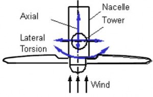
Definition of Vibration Directions [1]
The effects of the aerodynamic rotor imbalances are often underrated and/or misunderstood. Such aerodynamic imbalances can be caused by blade angle deviations or blade damages. The angle deviations or damages lead to varying aerodynamic characteristics among all three blades, which cause the appearance of different forces on each blade. A simple vector addition reveals the basic principle of the origin of lateral vibrations. Based on different aerodynamic characteristics, each of the blades generates different circumferential forces under the influence of the wind. The resulting force, represented by the red arrow, causes mainly torsional and lateral vibrations.
Refer to Figure 2 for more detailed information.
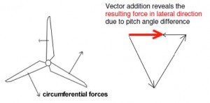
Figure 2: Principle of reduced torque but increased later vibration due to Aerodynamic Imbalance
The aerodynamic imbalance is proportional to the squared wind speed and therefore changing with the operation conditions:
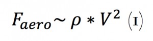
Based on the dynamic character of the aerodynamic imbalance, the resulting lateral force cannot be eliminated by the installation of counterweights. Like the lateral vibrations the torsional vibrations also increase with higher rotation speeds and are therefore directly dependent on the operating conditions.
For the elimination of the aerodynamic imbalance it is important to take measures which make sure that the aerodynamic characteristics of each blade are similar to each other. This would result in equal circumferential forces and a reduction or even elimination of the resulting lateral force.
Such measures are the examination and correction of the rotor blade angles and the repair of damages blade surfaces.
Mass Imbalance
Rotor blades of WTGs are unique pieces. No blade equals another blade. The rotor blade production is not completely automated and is basically carried out manually with the help of master mould. This has negative effects on the fabrication precision in terms of form, weight and weight distribution.
The mass imbalance of a rotor blade is dependent on the weight and its distribution over the length of the blade. Figure 3 shows the principle of the mass imbalance. Formula 2 shows the exact correlation of the factors.
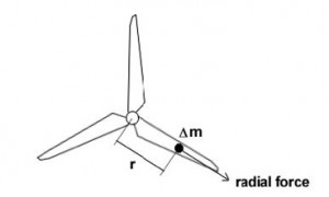
Principle of Mass Imbalance
![]()
The resulting radial force Frad equals the product of the mass deviation Δm, its radius rΔm and the squared rotor speed. It increases mainly the lateral vibrations. For the elimination of this imbalance, counterweights can be installed.
In order to avoid mass imbalances of the rotor due to different weights of the blades (Δm), blade manufacturers weigh the blades and determine their centre of gravity (CoG) after the production. They arrange blades with the same static moment to a blade set. Therefore, at the time of erection of the turbine, the static moment of all three blades should only vary slightly (within the set tolerance).
However, at the assembled rotors, field studies show that mass imbalances exceeding the limits are present at about 30% of the turbines. This value is based on analyses of the German rotor balancing specialist BerlinWind [2].
Imbalance Limits from Design Standards and Guidelines
For the dimensioning of all components of wind turbines, several assumptions regarding the occurrence of static and dynamic loads are made. In order to calculate the extreme load conditions, extreme limits of characteristics regarding the environmental conditions and regarding the turbine conditions must be assumed. Within the assumptions for the turbine conditions, a value for the maximum blade angle deviation and a value for the maximum rotor imbalance is set. The WTG-type and its components are designed to withstand all these conditions for a period of 20 years.
A type certificate, in which the assumptions of the operating conditions are set and the calculation of loads are described, must be prepared for each turbine type according to the standards and norms in force which are – amongst others – the following:
- • DIN EN 61400-1:2005, Wind turbines – design requirements, 3rd edition, 2005
- • Guideline for the Certification of Wind Turbines Germanischer Lloyd, Hamburg 2003/2010
- • DIBt Guideline for Wind Turbines for the German Civil Building Authority, (Richtlinie für Windenergieanlagen, Einwirkungen und Standsicherheitsnachweise für Turm und Gründung, Deutsches Institut für Bautechnik, Berlin, Editions 2003/2012.
Consequences of Rotor Imbalance
Lifetime Consumption
Any level of vibration leads to lifetime consumption of every component of the WTG and consequently leads to damages and even total loss of the component. However, the components of the turbine are designed to withstand the normal vibration for 20 years of operation. But increased vibrations caused e.g. by rotor imbalance above the critical limit can cause a faster lifetime consumption and component damages long before the attainment of the planned lifetime of 20 years. On the other hand, effective and periodic maintenance can extend the planned lifetime. Currently, no reliable data of the maximum lifetime of the 2-3 MW turbines class is available simply based on the fact, that the first turbines of this class were erected no longer than 15 years ago. However, it is certain that a large number of the erected turbines show component damages a long time before the reach of the maximum lifetime. Components like blades, bearings, gearboxes, coupling, generator and even foundations show significant wear signs and damages. Often the components must be replaced.
The reasons for this early consumption of the lifetime are multifaceted but it is evident that a rotor imbalance has a major impact on the lifetime consumption.
Damage Losses and Down Times
Probably the greatest benefit of a rotor imbalance investigation is the possible avoidance of damages. The replacement of damaged components is not only heavily cost and time intensive but also often requires special equipment like a large crane, which is not always available. The costs for such a component replacement vary on a broad range and are depended on various conditions, such as the operation, maintenance and service agreement of the turbine supplier, the spare part stock, the availability of other necessary tools and equipment and the missed earnings due to the resulting down time. For that reason Terrawatt is not able to number the economic benefit of the rotor imbalance investigation in a reliable manner.
However, already the avoidance of one damaged main component justifies the rotor imbalance investigation of several turbines.
Power Output Reduction
Rotor imbalance also causes a reduction of the power. However, the percentage of the power reduction and the effect on the energy yield of the turbine is difficult to quantify since several other characteristics have an effect on the energy output. It is evident that blade angle deviations mainly cause a reduction of power output during partial load operation of pitch controlled turbines. Depending on the angle deviation the energy yield could be significantly affected. Based on own experiences Terrawatt estimates that an angle deviation of one blade of 1° cause an energy yield reduction of approximately 2-3%.
Affected Turbine Numbers
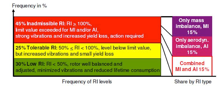
Terrawatt is not aware of an extensive and detailed investigation of rotor imbalances of a large number of WTGs. However, several small companies released some statistics of their measurement campaigns and case studies and the consultant as well has some experience regarding that issue. The German company BerlinWind has performed balancing analyses of more than 1000 WTGs and prepared an official paper for the EWEA 2013 fair in Vienna [2]. The presented results are quite astonishing. BerlinWind came to the conclusion that 45% of all investigated turbines show inadmissible rotor imbalances. The reasons for the investigated imbalance lay to equal shares in the mass imbalance and aerodynamic imbalance. Both types of imbalances were reported at 15% of the turbines.
Based on this statistic a total of more than 100 turbine of the Fantanele wind farm are ex-pected to have significant rotor imbalances. Two thirds of these turbines should show significant blade angle deviations, which can be detected by the consultant.
Bibliography
1 Deutsche Wind Guard Dynamics GmbH, 2008: Paper “Effect of Aerodynamic Rotor Imbalances on Energy Yield and Operating Life”
2 BerlinWind GmbH, EWEA 2013, Vienna, PO.ID 128, Handout “Payback Analysis Of Differ-ent Rotor Balancing Strategies”
3 BerlinWind GmbH, EWEA 2011, Paper “Improving Performance of Wind Turbines through Blade Angle Optimisation and Rotor Balancing”
Annex
A – FW103, damaged leading edge blade 1
B – FW103, damaged tip blade 2